ΜBITX
Notes on µBITX assembly and use.
Assembly
Parts that took some time to decide on approach to:
- Case: used a cookie tin from Goodwill for $3 as a case.
- Mic assembly: TODO
Antenna setup
20m dipole
Inverted V dipole made with Amateur Radio Supplies 20m dipole antenna wire (two 18' strands, trimmed, wrapped around insulators, strung up in attic) and 450Ω window line.
- Originally was sent two 16ft strands, which is really too short. Customer service was great and sent me the 18ft strands and a prepaid return envelope for the 16ft strands.
QRPGuys Multi Z Tuner
QRPGuys 12W dummy load
- Still no luck getting power measurements working.
- dummy load works when diode is removed (??)
Items from QRPGuys took about 2 weeks from date of order to arrive.
7-band OCF dipole
Ordered 7-band OCF dipole from gniklat1 on eBay.
Mods perfomed
Fuse before diode
Applied this fix during initial assembly.
The diagram there appears to be labelled incorrectly, though.
Have blown the fuse twice (first time forget, second time transmitting on 40m with untuned antenna) quite a few times, so it seems to work.
Mitigating heat on LM7805
I started by adding a small 5V switching power supply before LM7805. This created a ton of noise on RX, so I took it out.
Instead, I relocated LM7805 to case (up against case and screwed to it). The first time I got the leads switched, though, and smoked the nano, so had to replace that.
This arrangement seems to dissipate heat nicely.
I also have a heatsink in some old electronics that I've been meaning to try out too.
Dim the LCD
As documented here. At first it had no effect, but then found I hadn't cut the trace between the two leads first, which I did 2018-09-06.
CEC firmware
After getting some extra nanos, I flashed one with CEC firmware. Works great!
TX LED
Soldered up red LED per BITX20 message 46853 on 2018-09-06. Works great!
Leveling out power
Replaced some of the transistors (etc.) per this solution:
- Replace the 2N3904 transistors in driver stages (Q911, Q912, Q92, Q93, Q96, Q97) with 2n2222 transistors (in TO18 metal can),
- Parallel up R941, R911, R96, and R942 to get 11 ohms each by placing a 22 ohm resistor across each existing resistor (stacked 1206),
- Replace Q90 with a BFR106 transistor,
- Increase R81 to 2.7K,
- Change C81 to 470 pF.
Reducing spurs
Reducing harmonics
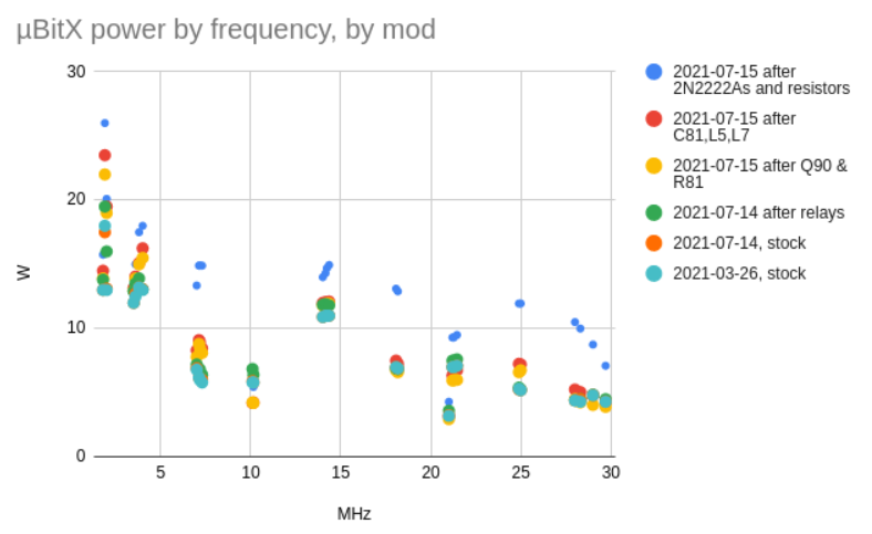
Power measurements
- Before and after the 3 mods above (levelling out power, reducing spurs, reducing harmonics)
Mods planned
Other things on wish list
SWR meter- YL got me a DAIWA CN-501H for my birthday, 2021-03
- Antenna analyser / antuino
- Red-on-black or amber-on-black display (for night-time operation)
- And/or a 6-8 digit LED display
- More buttons - I like PH2LB's approach!
- band up, band down, left/right digit selection for tuning, ...?
- Foot-pedal controlled TX
- Have obtained an old (working) foot pedal switch for this purpose (edit: now have two)
- Some sort of audio pre-processing?
- Fix filters??
